
1996 ~ New Logo — Fully Dedicated Business Direction:
The original art for the new Waveform logo of 1996 was created by the ad agency madvertising [ a young enthusiast husband & wife team, located near Hamilton, ON] in the winter of 1995.
“In its openness and simplicity, the emblem demonstrates a willingness to evolve, a hospitality portal if you will. The stylized W houses the inclusiveness of an open listening triangle, superimposed on the logo. The power and clarity of the image promised a first class product. The stylized AV and curved R reflected the artistic content of the product. The serif font was indicative of John Ötvös’ high regard for tradition.”
1996 ~The Mach 17: flatline fidelity
In 1995, I had chosen to go full-time into loudspeaker development, manufacture and marketing. For the past 11 years, the cabinetmaking business model of routine but customized kitchens, vanities, hand railings, built-ins, with the odd pieces of custom furniture had supported through subsidizing Waveform, as those were the mainstays of income generation.
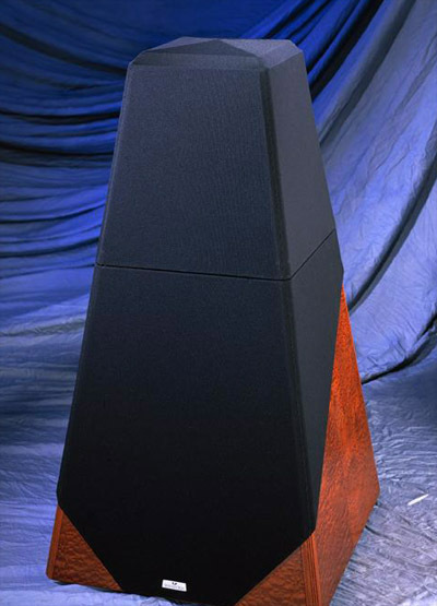
Quilted Makoré + twin grilles – 1998.
The pioneering work in developing the Mach 13 eventually resulted in the Mach 17, with its mid-range and tweeter speakers housed in a tiltable and turnable egg, with fully discrete 3-way electronic crossover.
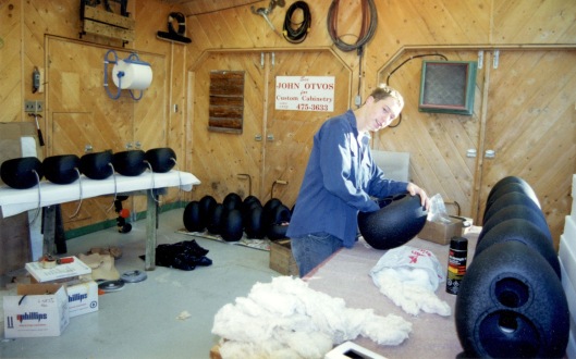
Todd applying the interior damping on the aluminium casting during processing – 1999.
“As an uncompromising commitment to its product and to its clients, Waveform makes only one model and constantly investigates new methods and materials in order to improve acoustic accuracy, yielding a greater sense of realism for the listener.”
In mid 1995, Claude and I set out to build yet another kingmaker or the very best performance related speaker that technology would allow for that era. As has already been mentioned above, the Mach 13 was the test mule to see what we could extract from the drivers chosen. If you are a small company wishing to make a speaker, you almost always use OEM drivers or Original Equipment Manufacturer.

Barry Mitchell QC’in’ passive component configuration in the office with the Audio Control SA-3051 analyzer. Cabinets were quarter-sawn white oak – 1999.
Barry relates this story missing from my recollection:
All this means in common parlance is that a specialty company like Audax, Vifa or Philips has made the drivers, and you have bought them for use in your own contraption. hahaha I was tiring of the large physical shape, the many hours needed to fashion the wooden box, as I thought something modular might be the ticket. Paul at PSB had already done this with his offerings. Claude and I fully concurred, we were in sync that dispersion was the key to an accurate dynamic and neutral sounding loudspeaker. Claude told me a story, that decades ago in the 1960’s, some Japanese audio nerds, cum scientists, had built a 1 metre tall egg as a 4-way contraption. It was very linear according to Claude’s memory. I stuck this idea in my craw and sometime later had a conversation with my buddy, John Meyer of the still existent Newform Research which, continues to manufacture ribbon or linesource loudspeakers.

John Meyer’s own conglomerate plastic casting, was used as a test mule for the mid & tweeter drivers we had chosen from the Mach 13 – 1995.
John Meyer told me that he had experimented using an egg shape although he did not produce anything commercially. He even went so far as to patent the shape, but only in Canada if memory serves. I asked him to allow Waveform to use the shape and he agreed. No money changed hands. This is how friends are with each other.
Ruffhouse Records & Posthorn Recordings:
Waveform was able to snag two more feathers for hat decorating with Mach 17 purchases by two lesser known recording companies.Joe Nicolo of Ruffhouse Records, originally located in Conshohocken, PA was probably best known for his Fugees and Lauryn Hill releases. Joe was the first American to purchase a Mach 17 system. Joe heard the 17’s in NYC at the Stereophile show in 1996, ordering a pair on the spot. http://www.ruffhouserecords.com/
Later, Jerry Bruck, of Posthorn Recordings, purchased a pair of Mach 17’s http://www.posthorn.com/ in NYC.
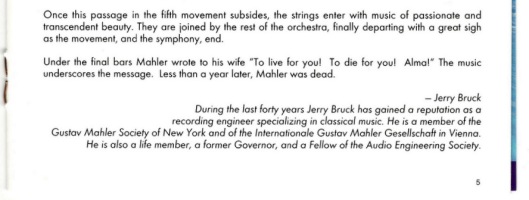
Jerry Bruck created the liner notes for Telarc’s rendition of the Mahler 10th Symphony – 2000.
The following R.A.H.E [Recreation Audio High-End] post is over 20 years old and I don’t know where to find the server that it’s stored on. It also seems as though that particular forum has gone the way of the dodo bird.
| The Ten Commandments |
| The following paper was composed in response to a query posed on R.A.H-E. by Jeff Bernhard some time ago when I had more time to write. From: (Jeff Bernhard) Date: 1998/04/02
To save a soul, I can’t understand why there is such reluctance on the part of supposedly passionate audiophiles, to do side by side comparison tests with matched levels and lights out. It’s almost as if many people don’t want to know the truth. That there are virtually no magazines doing this on a consistent basis is easy. What’s in it for them, a reduction of ad revenue? Last fall, I used the analogy of drag racing, the purest form of racing ever invented. The quintessential A/B side by side go for broke, who’s quicker, time and speed differences, no ice dancing judge in the grandstands. 🙂 I also listed a very simple procedure to carry this out in your home regarding loudspeakers, with no expensive special equipment. The mono blind comparison test. Sigh! <So John, what matters, and what doesn’t?> A very fair question. Of necessity this post is lengthy and the primary focus is on what does matter. Pardons all around. I have made every attempt to use language and phraseology that does not isolate uninformed readers. Since I am not the mathematical wizard behind the designs, (that’s why we commission engineers to work within the theory) there is no attempt to demonstrate who has a more sophisticated grasp of ‘the elements’. It is absolutely crucial for enthusiasts to understand the basic underpinnings of established acoustic theory, so that they will have a more informed knowledge before committing hard earned money for a new purchase. The following notes are taken from the graph explanations and the mission statement within the Mach 17’s owner’s manual and embellished for the readers of RAH-E. As a technology driven firm, the design parameters in order of their importance are as follows:
The king of curves, in all his accuracy.
This factor cannot be represented by a frequency response graph.
A] MODES: No manufacturer can sell people rooms but they are an intrinsic part of the room/speaker interface. Over the yrs., there have been several attempts to define the physical measurements for good rooms and thereby reduce the influence of standing waves. There has been little real progress in this area for the modes are usually just shifted around to other areas of the spectrum. All that is important, is that large rooms spread the modes out more evenly and therefore reduce their intensity. Small rooms by their nature aren’t able to do this and so midbass impact is more noticeable on popular music (that 50Hz drum) but on classical music (baritone voice or instruments) sounds are often perceived as bloated overly warm and simply ill-defined. B] RT60 or reverberant decay. The IEC standard was set some yrs. ago between 0.3s and 0.4s. The optimum for speech intelligibility is 0.35s in the midrange, where most of the music resides. Deader rooms (0.3s or less) reveal more low-level information and a more compact image because the direct sound is louder. However, the trade off is that these rooms are not as dynamic as a more lively room (0.4s or higher) and also require more amplifier power to achieve a commensurate SPL. Ultimately, we try to get our measurements to fit the theory without listening. In that sense, JD (John Dunlavy) and I agree that a speaker can be no more accurate than when it was first designed. An audiophile anathema eh? In my opinion, this is the opposite of designing a speaker the way JD or JT (Jim Thiel) do, with their phase and time priority, of forcing the theory to fit an excellent set of measurements in the time domain, and then telling the world that other products aren’t as accurate because they don’t have equal time domain measurements. JT doesn’t tell the world his are more accurate. He is the quintessential southern gentleman. This is the key to your understanding of why our design methods are different. I’m not saying that the Dunlavy speakers aren’t good. The true meaning of accuracy can only be neutrality, the system that reveals the greatest differences between the software. I think that statement is part of our religion. Since music is primarily transient by nature, great sound as it applies to our ability to hear is about the threshold of audibility. Good name for an amp, Threshold i.e. I think it is high time for the phase perfect people to give an accounting for why the ear is more sensitive to time than it is to level, in a typical room with many different reflections and reverberations. Also, how can these designers claim with a straight face, that their speaker products with their wacky lobing patterns are true point source products? Come on John Dunlavy, I gave my 2 hrs. this morning. Phew! How’s that Jeff? That’s enough typing for this week.
|
The next version was a clumsy and very heavy, thick wall aluminum casting. This one lasted one production run. Then we finally hit a homerun with a thinwall aluminum sand casting + CNC milling of the rebates for the tweeter and midrange drivers.

LMS employed for all inhouse QC. Calibrated mic, courtesy of Claude. Floor bounce caught on heavy basalt fibre pads. 1 M standard measurement, not exactly midway between floor & ceiling – 1998.
The initial iteration of the movable tilt ‘n turn egg was made using laminated MDF. [Medium Density Fibreboard] I had another local Brighton, ON buddy, Don Oakley of Oakley Woods Croquet turn them on his giant lathe. Until Don got the rotating speed down to below 300 rpm, some flew off, a few through the overhead window. hahaha
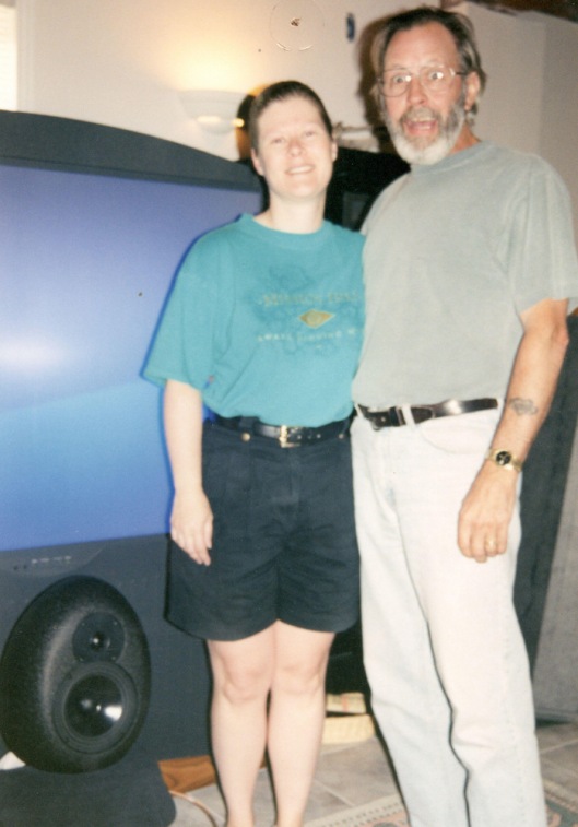
Catherine with hubby Barry Mitchell hammin’ it up for the snapshot after I gifted them with an MC CC as recognition for all the support, both financial and emotional through their purchases. This man has staying power for me! Bless you, buddy. – 2000.
I also went through several iterations of the box using different methods to attach the 4 sides as it was a tapered quadrilateral shape. Back then, there wasn’t much in the woodworking vein that I did which was easy. 🙂 It wasn’t so much the technical challenge as it was form following function. The egg of approximately 12 ̎ in OD, had to match a largish sized box for the twin 12 ̎ woofers. In order to obtain the required volume for very low bass extension given a boost in the electronic crossover, I wanted the form to taper to meet the egg platform. The ‘roof’ of the sub enclosure, had to absorb frequency reflections from the twin drivers in the egghead. Voila, the transition molding of opencell foam and grille cloth, which housed the plastic tilt ‘n turn mechanism, originally sourced from a CRT computer monitor.

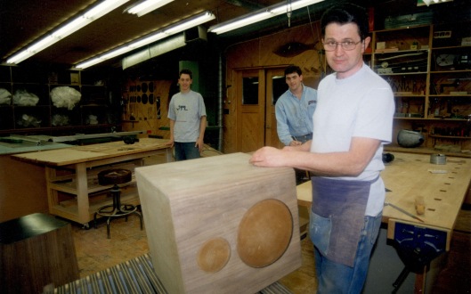
The initial production run of Mach 17 loudspeakers with their wooden lathe turned heads, await the Bryson built 3-way electronic crossover prior to shipment. Clean & shiny floor eh? hahaha Some visitors even removed footwear when arriving. Ahh, respect! 🙂 – 1996.
Anechoic Chamber
Also known as a ‘Free-Field Room’ or ‘Free-Space Room’, this chamber is used to limit sound reflection and external noise.
“When placed within such a room, the pure acoustical reproductive properties of a speaker – uncoloured by any room influences – can be accurately measured. Based on these measurements, predictions can then be made about a speaker’s performance under normal listening conditions and its acoustic transduction further refined.”
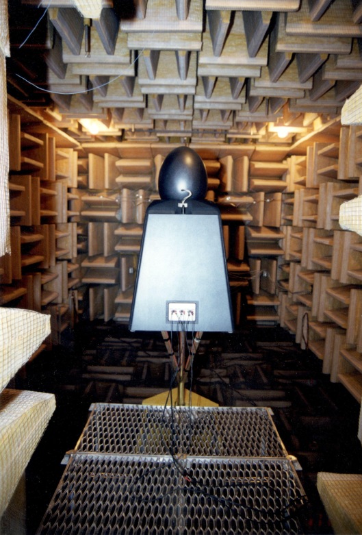
Mach 17 in the chamber Notice the three paired terminals on the lower rear for individual amps. No other speaker company in consumer audio did this. BTW, those fibreglass acoustic wedges are a metre deep at floor level as elsewhere in that room. If you listen closely, you can hear your blood flowing, hear your lungs pumping too. One ought never to pass wind in there though! hahaha – 1998.
Bryston Ltd. Electronic Crossover:
I chose Bryston, a longtime CDN company, within both the pro & consumer audio industries to manufacture the dedicated 3-way active electronic crossover. Waveform was an authorized Internet dealer and I felt aligning myself with this company, might give the brand some added caché or credibility, as the word went in the high-end community. This alignment also allowed Waveform to sell Bryston amps of differing configurations to enhance our income. At the time, I believed there were differences in sound quality between amps. Today I know better than this old upselling mantra. Often in audio, what offends the eyes does not disturb the ears, as has previously been mentioned, was a favoured expression from Dr. Floyd Toole.
This is why so many audiophiles could not make a buying decision without a great review from a major high-end magazine. If only those very same auds could figure out how to park their purchases in the driveway huh? hahaha Continuing with the need to sell and grow the company, we also made XLR and RCA cables as well as custom length speaker cables using the finest Swiss Neutrik connectors available. I also gained authorized permission to be a Kenwood dealer, hawking their 6-channel amps that were a phenomenal device. Even though they were fan cooled, when I placed my ear against the massive amp, no audible whirring could be detected. Of course, a $1,500 amp replacing $12K of ‘discrete’ electronic amplification is anathema in the loopy world of high-end audio . . . then and now.

The 3-way Mach 17 electronic crossover was a discrete, custom design exclusively manufactured for Waveform by Bryston Limited. It housed over 1200 individual parts. The chassis size was determined by their preamp at the time. This is the first public admission that unfortunately, it lacked enough physical room to add one more equalization stage, so that the production version never quite matched what Claude had developed in the chamber with his 4-way S.O.T.A mule. Very close, but no cigar. Such is life. Today, I would have someone design a digital 3-way amp with an IC crossover + room correction, all in one chassis – 1996.
“Originally designed in 1995, with the first production versions released for sale in the summer of 1996, the Mach 17 has been praised as among the very best loudspeakers in the world. The speaker has garnered five 5-star reviews, both within the print media and on the web, including a Class ‘A’ rating from Stereophile magazine.”

The original listing appeared in 1996. Now, nearly 22 years on and still unequaled. D’ya tink I should apply to Guinness World Book of records? hahaha – 1999
“We have been consistently lauded for our demonstrations at consumer HI-FI shows, both in Canada and the US, as well as our very successful tour of audiophile societies. Four years later, there has yet to be a request for a refund since all Waveform loudspeakers are marketed direct. Four years later, there has yet to be another speaker from a competing company that combines as many features into one product as the Mach 17. This is our niche. True performance – speakers built for a lifetime. The explicit design criteria for the Mach 17, was to follow the point source theory of acoustic propagation to its logical extension, then build a transducer, fully utilizing all the known electrical and mechanical techniques to render the highest form of development and technology available.”
It was an impossible sell to auds ’cause they could not fathom a speaker in this “A” category costing so little. The aud was not my market; the music lover was. Sadly, far too many then, even moreso now, could not afford this purchase.
1998 Product Line Expansion:
As time advanced, in 1998, DVD burst onto the audio/video scene leaving VHS as well as the ole Beta VS VHS format war, dead in the water. Listeners and viewers wanted more than simply a stereo pair of speakers. Waveform met that challenge with 6 new products. We also invested in a CNC router [Computer Numerical Control] for the manufacture of all the wooden panels for the woofer boxes. We learned how to engrave and cut our logo into the plastic faceplates + all the milling for the aluminum baskets on the midrange drivers. We made foam gaskets and trim rings too. The machine paid for itself in that first year of heady production. My son Todd programmed all of this while still a teenager. A good kid then; a fine man today. Bless you, son. >:<
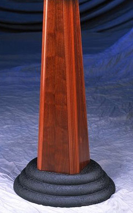
MC Tower with cast aluminum base for stability and appearance. 8 pieces of wood to fasten together.
“MC means Multi Channel, Music and Cinema or Master of Ceremonies – take your pick. It is Waveform’s only shielded loudspeaker. As such, it can be used as a centre channel, or as the main L & R channels in an HT system, surrounding a monitor or as multimedia loudspeakers for a computer-based workstation. The Mach MC is perhaps the best example of the point source principal. When one speaker mounted on our MC Tower is positioned in the middle of a room, and a listener takes a 360° path around, it is easily apparent how much sound is radiated to the sides and rear. Additionally, listeners will note how similar the sound remains all around the loud-speaker. This is what we affectionately like to refer to as the proof is in the pudding. Simply stated, the point source theory is defined as ‘identical loudness in all directions’.”

4″ ported MC Sub based on the identical 10″ Vifa woofer a solid unit.
We designed and engineered a CC or centre channel that could double as sides, surrounds, main L & R + back channels. The computer configurations were becoming ever more numerous and therefore more complicated in setting up the optimum experience of ‘you are there’ or ‘the suspension of disbelief’. Envelopment became what people really liked to hear, whether music or film. This encircling of sound became the defacto public preference. Waveform had to respond in order to continue to sell product. When DD or Dolby Digital became the defacto standard, as it still is for DVD, people wanted that standard as opposed to Pro Logic with the receiver steering the sounds through an arbitrary algorithm. DD meant that the audio engineers had systematically decided what sounds would be steered to what channel, based upon what they were hearing in the control room during a recording session, or later in the editing space. I refuse to enter the silly debate about the usage of centre channels as the folks who wage that war prefer old-time stereo.
Todd, Tobe & jayöh making boxes. I still retain the whale clock above Tobe’s head – 1999.
We made an MC single channel speaker used in multiple locations, a genuine MC.1 sub, an MC System consisting of 5 MC’s and 3 MCwoofer boxes, one earmarked as the .1 or genuine subwoofer as well as the MC Tower. We also made the Mach Solo, which was a single channel driven, passive speaker with a 10 ̎ woofer, flat to 36 Hz, encompassing the identical mid and tweeter as its more expensive big brother, the Mach 17. There was an MC glass plate shelf and an MC wall bracket, all done in an exquisite textured finish [black alligator powder finish] by a shop over two hours drive, that was manned solely by women. A new 4-colour brochure to enhance these offerings to render Waveform, the company, appear professional, stable and reliable. Sadly, all this was to prove not enough.
| Features of a Good Listening Room |
The crucial determinant The listening room has always been the unknown, non-sellable component in the reproduction chain. In situations with wide dispersion loudspeakers, due to intense room interaction, the room becomes perhaps more important than the recording. This little known fact may seem like heresy to the uninitiated. In the old days before LMS, FFT analysis and MLSSA, handclaps were measured with stopwatches to determine the RT60. Fairly rudimentary, but it worked. As audiophiles, we oftentimes read about the necessity to maintain a “good room”, but are seldom provided with a standard or reference to what that entails. The key question Simply stated, if one moves to the center of the playback space and either claps hands or calls out in a loud voice, any trace of sound remaining after the initial proclamation is echo or decay. In an anechoic chamber, there is none in the principle frequency range. Smaller chambers have some problems in the very lowest cycles below 30 Hz. This lack of echo is what defines these places as ideal for development work with loudspeakers. Room conditions Open doors into adjacent rooms are some of the best bass traps. Allow the first wave to escape without it being returned. You’ve already heard it, so let it go. Of course, this assumes that one is not bothering occupants in adjacent spaces. Bookcases and other wall protrusions, tall and bushy plants, high sloped ceilings, thick carpets on the floor, over stuffed seating arrangements, are what is required. Window coverings are crucial, with the best absorption coming from heavy velour draperies. Any objects which can act as absorbers or diffusers should be pressed into service. Irregular works better than regular. Soft walls such as gyproc on wood studs are superior to concrete block and brick. Also, a wood floor will allow for better propagation of bass over a cement pad. With any boundary, the initial wave is returned out of phase, meeting the oncoming in phase wave of the same frequency causing cancellations. These cancellations also cause standing waves throughout the listening space. This bad stuff happens on ‘soft’ and on ‘hard’ surfaces with the important difference being, that with the soft boundary, some of the initial energy is absorbed so that when it is returned out of phase, the cancellations are much smaller and the resultant standing waves are not so pronounced. Hard surfaces like concrete do act as low bass reinforcements, so there is some give and take here. No one expects all those who live in warm climates to lose sleep over their homes with slab floor constructions. Oddly enough Many speaker designers don’t pay attention to the off-axis dispersion of their transducers, especially in the upper mid and high frequencies. Others realizing that theirs too is less than optimum, use felt, tunnels, shelves and other projections to direct the sound away from the room boundaries and “channel” it toward the listening position. As a group, audiophiles have lost sight of how a point source loudspeaker should be defined. In real life, a singer or musician would sound the same throughout most of the listening space for the members of the audience, whether seated or standing. If a speaker can be made to mimic more approximately this aspect, then this should be the definition of a point source. Tonal characteristics at equal energy levels, from all reflections with a similar nature to the direct sound. These days we hear a lot about the coming global culture of peace, democracy and knowledge. It is my fervent wish, that we with computers, discuss in a serious manner acoustic problems, using simple language without any intellectual superiority or competitive product malignment, thereby working to shed light on acoustic and psychoacoustic subjects, kept dark by non-discussion in recreational forums, whether print or electronic. These topics are crucial for those of us with the inclination for progression. We who listen are being trampled by those who watch. For those of us who are wired, it remains to be seen whether or not we become truly connected. Sincerely,
|
Go to Waveform pt3 of 3

A very interesting read. Particularly the NRC research and the work of Dr. Toole along with his followers. As an engineer I fully agree with your comments on speaker evaluation.
Sad that the industry continues to promote the next best thing even when it is usually just another variation of snake oil. Still over the years there has been steady progress towards better sound it’s just that there are almost as many steps backwards as there are forwards.
We owe a dept to those who really do care about the sound.
Best regards
Drew
Thank you Drew for your comment. Yes, there were many of us taking the theories and putting those ideas into products for sale. Sadly, how so many folks listen today through single-centred small speakers is a travesty, considering it’s a regressive step back from stereo and a country mile from any form of multi-channel surround sound where the objective is envelopment of the listener in his own home. We must also realize that it’s a business, so nothing should remain in the way of a sale, any sale.
So wonderful to read this whole story of Waveform. I purchased a pair of Solos in May 2000, perhaps the last pair at full retail. They were the best speakers I ever owned, and perhaps maybe ever heard. Life changes came and I had to send them to a new home after some time. Pity that I could not have found a way to keep them. I wish I still had them!
And no successor speaker by anyone has ever come, not even a DIY attempt.
All the best to you John.
Steve
You’re one of the very rare handful of people that want to get it done right for a real person who will enjoy it. You had all the right engineering things in place… no …interfering early reflections …taking care of the room …adjustable position for the mid range treble unit …and multiple amps and sharp crossovers …way ahead of your time. And probably still ahead of your time and a few people started to do it in the last seven years….i so I wish I could hear those mach 17s in San Jose…I wonder what kind of drivers you would prefer to use now …what materials?
Grodun; Thanks so much for reading the history of Waveform. Life is about experiences. There is no definitive proof for truth in any field of endeavour, since there are far too many variables that interact, which, is all aside from the ones behind the veil, that we cannot know or understand, how they are indelibly entwined and interleaved. For instance, I follow an evidence based diet. Nearly 40 years ago when I began the loudspeaker odyssey, I looked for evidence in how to base design, engineer and then manufacture a great sounding transducer. There were many hands in the mix, so to speak. That has been documented. Inititially,that curiosity led me to Canada’s NRC and the rest as “they” say, is l’histoire. 🙂
hello Sir, i have been looking for information on your 17 loudspeakers for quite awhile. Years ago, i could not afford a pair, and now that i can, there are none to be found. Are there any plans to be purchased ? Wonderful speaker , way ahead of its time.
Waveform has been closed for nearly 22 years. Try some of the audio sites.